

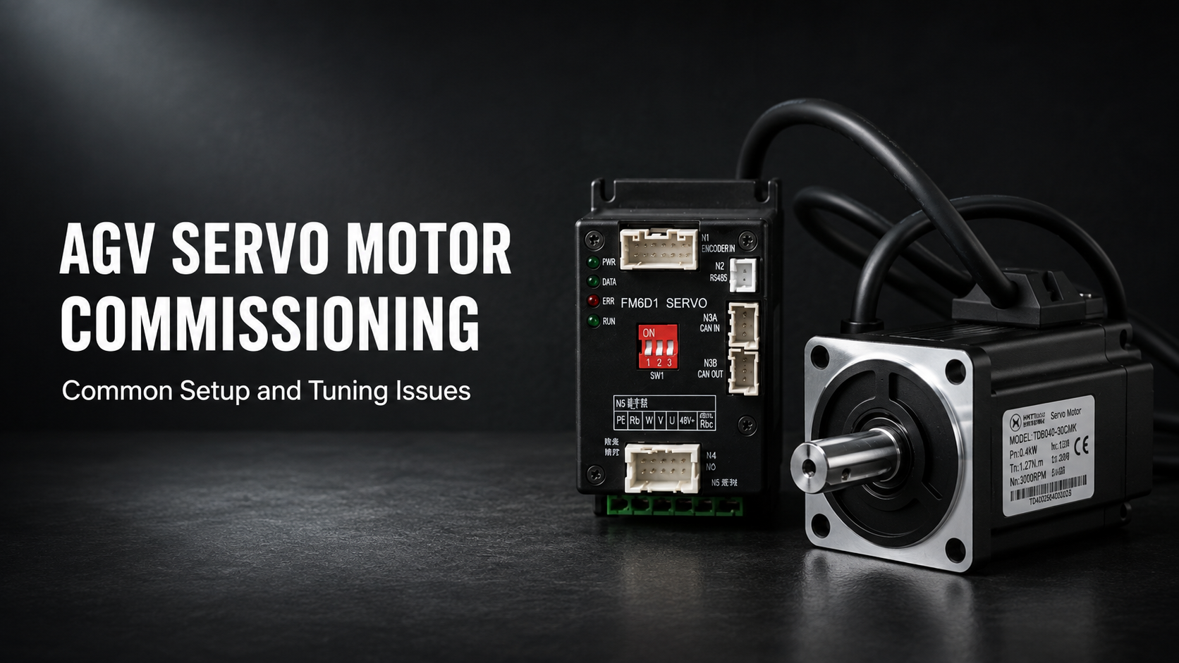
Bir test tezgahında kusursuz çalışan bir servo motor, AGV şasisine cıvatalandığında, gerçek bir şanzımana ve tekerleğe bağlandığında ve yüklü bir aracı depo zemininde hareket ettirmesi istendiğinde çok farklı davranabilir. Bu aşamada ortaya çıkan sorunların çoğu motor arızası değil, devreye alma sorunlarıdır. Yanlış sırada bağlanmış bir faz, eksik bir hat sonlandırıcı, motor güç kablosunun yanından geçirilen bir enkoder kablosu veya boş bir araçta ayarlanmış bir kazanç değeri; hepsi donanım arızası gibi görünen ancak kurulumda tamamen düzeltilebilir belirtiler ortaya çıkarır. Bu kılavuz, AGV servo motoru devreye alma işlemini aslında yapılması gereken sırada ele alır ve en yaygın belirtilerin size ne anlattığını açıklar.
Devreye Alma Neden Tanımlanmış Bir Sırayı Hak Eder
Devreye alma genellikle kurulum ile test arasında, kim yapıyorsa onun tarafından farklı şekilde ele alınan resmi olmayan bir adım olarak görülür. Bu gayriresmilik, önlenebilir sorunların çoğunun kaynağıdır. On beş dakika kazanmak için güç öncesi kontrolü atlamak, bir kablolama hatasını ancak motor yüklü bir aracı rafa sürmeye çalıştıktan sonra keşfetmek anlamına gelebilir. Enkoder geri bildirimini doğrulamadan kazançları ayarlamak, en başta hatalı olabilecek bir sinyale göre ayar yapmak anlamına gelir.
İlk Hareketten Önce Güç Öncesi Kontroller
Bu aşamadaki her şey, sürücü etkinleştirilmeden önce gerçekleşir. Bu, titiz davranmanın en ucuz olduğu ve acele etmenin en pahalı olduğu aşamadır.
Güç Kablolaması ve Faz Sırası
Güç vermeden önce motor faz bağlantılarını sürücü terminal etiketleriyle karşılaştırarak doğrulayın. İki fazı yer değiştirmiş fırçasız bir servo motor sadece ters yönde çalışmaz; sürücünün komütasyon yöntemine bağlı olarak kullanılabilir tork üretemeyebilir, aşırı akım çekebilir veya etkinleştirildiğinde kontrolsüz bir şekilde kaçabilir. DC girişinin ters çevrilmesi güç açılışında sürücüye hemen zarar verebileceğinden, besleme polaritesini de onaylayın.
Enkoder Kablo Yönlendirme ve Ekranlama
Enkoder geri bildirimi, yüksek akımlı anahtarlama elektroniğinin yakınında çalışan düşük voltajlı bir sinyaldir ve bu da onu sistemdeki gürültüye en duyarlı bağlantı yapar. Enkoder kablolarını motor güç kablolarıyla birlikte demetlemek yerine fiziksel olarak ayrı yönlendirin, ekranlı kablo kullanın ve ekranı yalnızca bir uçtan topraklayın. Bir ekranı her iki uçtan topraklamak, engellediğinden daha fazla gürültü enjekte eden bir toprak döngüsü oluşturabilir. Enkoder gürültüsünün belirtileri belirgindir: hareket olmadan kayan pozisyon sayımları, aralıklı takip hatası alarmları veya motor mekanik olarak hareketsizken dalgalanma gösteren hız geri bildirimi.
Fieldbus Sonlandırma ve Topraklama
CAN tabanlı bir sistemde, veri yolu ağın her fiziksel ucunda 120 ohm'luk bir sonlandırma direncine ihtiyaç duyar; bir tane değil ve her düğümde bir tane değil. Sonlandırıcısı eksik bir veri yolu, tezgah testlerinde kısa kablo uzunluklarında ve düşük hızlarda genellikle iletişim kurar, ancak tam uzunlukta bir şasi tesisatına takıldığında kesintili hale gelir. Bu, tam olarak temiz bir şekilde arıza vermediği için teşhis edilmesi en çok zaman alan arızalardan biridir. Sonlandırmayı varsaymak yerine fiziksel olarak doğrulayın ve tüm cihazların ortak bir toprak referansını paylaştığından emin olun.
Mekanik Doğrulama
Sürücüyü etkinleştirmeden önce, tasarımın izin verdiği yerlerde motor milinin elle serbestçe döndüğünü, şanzımanın motor yatağına eksenel ön yük bindirmeden doğru şekilde bağlandığını ve montaj bağlantı elemanlarının torklandığını doğrulayın. Motor bir tutma freni içeriyorsa, gerçek bir yükü tutması istenmeden önce frenin duyulabilir şekilde serbest kaldığını ve devreye girdiğini doğrulayın.

Başlangıç Parametre Kurulumu
Kablolama doğrulandıktan sonra, bir sonraki aşama gerçek donanımla eşleşen bir parametre setini yüklemektir. Birçok devreye alma sorunu, farklı bir motor için tasarlanmış varsayılan parametrelerle çalışan bir sürücüden kaynaklanır.
Motor ve Sürücü Eşleştirme
Motorun anma akımını, tepe akım sınırını, anma hızını ve kutup çifti sayısını kurulu olan motorla eşleşecek şekilde ayarlayın. Akım sınırı, AGV uygulamalarında özel bir ilgiyi hak eder: çok yüksek ayarlanırsa, sürücünün bir tekerleğin engele takılması gibi bir durma olayında motoru ısıl değerinin ötesine itmesine izin verir; çok düşük ayarlanırsa, araç tam yük altında normal hızlanma sırasında aşırı akım hatası verecektir.
Enkoder Yapılandırması
Enkoder tipini ve çözünürlüğünü motordaki geri bildirim cihazıyla eşleşecek şekilde yapılandırın. Yanlış darbe sayısında yapılandırılmış bir artımlı enkoder, hız ve pozisyon değerlerinin yanlış ölçeklenmesine neden olur; bu da tipik olarak komut verilenden farklı bir mesafe giden bir araç olarak görünür. Mutlak geri bildirim kullanan sistemlerde, yanlış bir ofset zayıf torka ve tüm hızlarda yüksek akım çekimine neden olduğundan, komütasyon ofsetinin doğru kurulduğunu doğrulayın.
İletişim Adresi ve Baud Hızı
Veri yolundaki her düğümün benzersiz bir adrese ve eşleşen bir baud hızına ihtiyacı vardır. Aynı yapılandırmadan birden fazla özdeş sürücü kurulduğunda mükerrer düğüm adresleri yaygındır ve sonuçta ortaya çıkan belirti (bir veya her iki düğümün veri yolundan kesintili olarak düşmesi) kolayca kablolama hatasıyla karıştırılabilir. Tüm düğümleri aynı veri yoluna bağladıktan sonra değil, önce adreslerin benzersiz olduğunu doğrulayın.
Hareket Limitleri ve Rampalar
İlk testler için maksimum hız, hızlanma ve yavaşlama limitlerini ihtiyatlı bir şekilde ayarlayın. Devreye alma, tasarım hızında çalışma zamanı değildir. Azaltılmış limitler davranışı gözlemlemeyi ve bir sorun varsa güvenli bir şekilde durmayı mümkün kılar; kararlı hareket doğrulandıktan sonra bu limitler kademeli olarak artırılabilir.
İlk Hareket Testi
İlk etkinleştirme, tahrik tekerleği yerden kesikken veya araç güvenli bir şekilde bloklanmışken yapılmalı; araç zeminde serbestçe hareket edebilir durumdayken asla yapılmamalıdır.
Yön ve Yüksüz Dönüş
Düşük bir hız komutu verin ve motorun beklenen yönde döndüğünü doğrulayın. Yön ters ise, bunu fazları yeniden kablolayarak değil, sürücü parametresinden düzeltin; bu, gelecekteki servis işlemleri için kablolamanın belgelerle tutarlı kalmasını sağlar.
Enkoder Geri Bildirim Doğrulaması
Komut verilen hızı bildirilen geri bildirim hızıyla karşılaştırın. Kararlı durumda yakından takip etmelidirler. Komutun sabit bir katı olan geri bildirim değeri genellikle enkoder çözünürlüğü uyuşmazlığına işaret eder. Sabit hızda gürültülü veya kararsız olan geri bildirim, enkoder kablolamasına veya ekranlamasına işaret eder.
Fren Sıralaması
Tutma frenli motorlar için, frenin serbest kalması ile torkun etkinleştirilmesi arasındaki zamanlama ilişkisini doğrulayın. Fren, hareket komutu verilmeden önce tamamen serbest kalmalı ve yalnızca motor durduktan ve tork hala uygulanıyorken devreye girmelidir. Freni çok geç serbest bırakmak sürücünün kilitli bir mile karşı itmesine ve hata vermesine neden olur; çok erken devreye almak ise frenin tasarlanmadığı hareket enerjisini emmesine ve erken aşınmasına neden olur.

Kontrol Döngülerini Ayarlama
Ayarlama, devreye almanın tekrarlayıcı hale geldiği yerdir. Amaç maksimum sertlik değil, aracın tüm çalışma aralığında kararlı, tekrarlanabilir harekettir.
Hız Döngüsü
Hız döngüsü ile başlayın, çünkü pozisyon döngüsü onun üzerinde yer alır ve kararsız bir hız döngüsü üzerinde iyi davranamaz. Motor komut verilen hızı minimum hatayla tutana kadar oransal kazancı kademeli olarak artırın, ardından kararlı durum ofsetini ortadan kaldırmak için integral kazancı ekleyin. Küçük adımlarla artırın ve her değişiklikten sonra gözlemleyin.
Pozisyon Döngüsü ve Takip Hatası
Hız tepkisi kararlı olduğunda, kabul edilebilir takip hatası (hareket sırasında komut verilen ve gerçek pozisyon arasındaki fark) için pozisyon döngüsünü ayarlayın. Bir miktar takip hatası hızlanma sırasında normal ve beklenendir. Önemli olan, kararlı durumda sıfıra yakın bir değere dönmesi ve bir hareketin sonunda uzun süreli salınım olmadan hızlı bir şekilde durulmasıdır.
Aşırı ve Yetersiz Kazancı Tanıma
Aşırı kazanç kendisini sesli ve fiziksel olarak belli eder: duruşta motordan gelen yüksek perdeli bir vızıltı, şaside gözle görülür titreşim veya araç durduğunda sönümlenmek yerine büyüyen salınım. Yetersiz kazanç ise hız değişikliklerine karşı yavaş tepki, hızlanma sırasında büyük takip hatası, durma noktalarında yavaş durulma ve bazı sistemlerde aracın düzgün hareket etmek yerine küçük artışlarla ilerlediği düşük hızda sürünme veya yapışma-kayma davranışı gibi görünür.
Bu iki arıza modu arasında tek bir doğru değer yerine kullanılabilir bir aralık vardır. AGV uygulamaları için, bu aralığın alt sınırına doğru hafifçe yanılmak, genellikle biraz daha yavaş tepki verme pahasına daha yumuşak, daha sessiz bir çalışma sağlar; bu da paylaşımlı bir insan-robot ortamında genellikle doğru dengelemedir.
Gerçek Yük Altında Yeniden Ayarlama
Yüksüz bir araçta ayarlanan kazançlar, yük eklendiğinde nadiren doğru kalır. Eklenen kütle, motorun gördüğü efektif ataleti değiştirir ve bu da sistemin aynı kazanç değerlerine tepkisini değiştirir. Ayar doğrulamasını her zaman aracın beklenen çalışma yükünde ve aralık genişse ideal olarak hem minimum hem de maksimum yükte tekrarlayın. Yalnızca bir uçta ayarlanan bir sistem diğerinde salınım yapabilir.
Ayarlama Sorunu Çözemediğinde
Bazı kararsızlıklar hiç de bir ayarlama sorunu değildir. Yansıyan yük ataleti ile motor rotor ataleti arasındaki oran çok yüksekse, hiçbir kazanç değeri kombinasyonu hem tepkisel hem de kararlı bir davranış üretmeyecektir; kazancı artırmak salınıma, azaltmak ise yavaşlığa neden olur ve aralarında kullanılabilir bir ayar yoktur. Bu noktadaki çözüm sürücü parametrelerinde değil, seçimdedir: daha yüksek rotor ataletine sahip bir motor veya yansıyan ataleti motor milinde azaltan farklı bir dişli oranı.
Mekanik rezonans da benzer bir durumdur. Belirli bir hız aralığı diğer hızların yapmadığı bir titreşim üretiyorsa, neden genellikle bir kazanç hatasından ziyade uyarılmakta olan yapısal veya aktarma organı rezonansıdır. Birçok sürücü dar bir frekans bandını bastırmak için bir çentik filtresi sağlar, ancak daha kalıcı çözüm titreşen mekanik sertliği veya bağlantıyı ele almaktır.

Diferansiyel Tahrik Çiftini Devreye Alma
Bağımsız olarak tahrik edilen iki tekerlek kullanan araçlar, tek eksenli devreye almanın gerektirmediği bir zorunluluk getirir: iki tarafın sadece kabul edilebilir şekilde değil, birbirinin aynısı şekilde davranması gerekir.
Her iki sürücüyü bağımsız olarak kendi optimum değerine ayarlamak yerine eşleşen kazanç değerlerine ayarlayın. Hafif farklı tepki özelliklerine göre ayrı ayrı ayarlanan iki eksen, düz bir çizgi komutunu farklı şekilde izleyecek ve araç amaçlanan yolundan sapacaktır. Ayarlamadan sonra, mevcut en uzun mesafede bir düz hat testi yapın ve sonunda yanal sapmayı ölçün; bu, kısa hareketlerde görünmeyen uyuşmazlıkları ortaya çıkarır. Ayrıca kontrolcüde yapılandırılan tekerlek çapı ve aks mesafesi değerlerinin fiziksel araçla eşleştiğini doğrulayın, çünkü bu geometrik parametrelerdeki hatalar, sürücü ayarlamasının düzeltemeyeceği yön sapmalarına neden olur.
Aynı kontrolü yerinde dönüş için de tekrarlayın. Kendi merkezi etrafında temiz bir şekilde dönen bir araç eşleşen tekerlek hızlarına sahiptir; dönerken yanal olarak kayan bir araç ise sahip değildir.
Yaygın Devreye Alma Hataları ve Neler Gösterdikleri
Devreye alma sırasında karşılaşılan hata kodlarının çoğu, her biri karakteristik bir nedenler grubuna sahip az sayıda kategoriye girer.
Hızlanma sırasında aşırı akım, genellikle gerçek yük için çok düşük ayarlanmış bir akım sınırına, sürücünün kendisiyle savaşmasına neden olan bir kazanç ayarına veya aktarma organlarında gerçek bir mekanik sıkışmaya işaret eder. Hatanın hareket profilinin tekrarlanabilir bir noktasında meydana gelip gelmediğini kontrol edin; tutarlı bir tetikleme noktası parametre sorununa işaret ederken, rastgele bir nokta mekanik veya elektriksel bir kesintiye işaret eder.
Yavaşlama sırasında aşırı voltaj, pille çalışan araçlara özeldir ve ilk AGV'lerini devreye alan mühendisleri sık sık şaşırtır. Araç yavaşladığında, motor bir jeneratör gibi davranır ve enerjiyi DC veri yoluna geri iter. Pil bunu yeterince hızlı ememezse, sürücü koruyucu olarak devre dışı kalana kadar veri yolu voltajı yükselir. Yavaşlama rampasını yumuşatmak, üretilen gücü azaltır; agresif frenlemenin işlevsel bir gereklilik olduğu durumlarda, onu dağıtmak için bir frenleme direnci gerekebilir.
Sadece uzun süreli çalışmadan sonra ortaya çıkan aşırı sıcaklık, anlık bir kurulum hatasından ziyade görev döngüsüne veya termal ortama işaret eder; aralıklı görev için boyutlandırılmış bir motorun sürekli çalıştırılması veya sürücü çevresinde yetersiz havalandırması olan bir şasi gibi.
Enkoder alarmları ve iletişim zaman aşımları neredeyse her zaman güç öncesi aşamada ele alınan kablolama ve sonlandırma sorunlarına geri döner; bu kontrollerin ilk seferinde dikkatlice yapılmasının nedeni tam olarak budur.

SSS
Bir AGV servo motorunun devreye alınması genellikle ne kadar sürer?
Yapılandırma hakkında ne kadar bilgi sahibi olunduğuna bağlı olarak değişir. Kanıtlanmış bir parametre seti kullanan tekrar eden bir yapı hızlı bir şekilde devreye alınabilirken, yeni motorlar, yeni bir şanzıman oranı ve alışılmadık bir kontrolcü içeren ilk prototipin devreye alınması, zamanın çoğunun ilk kurulumdan ziyade ayarlama tekrarlarında harcanmasıyla önemli ölçüde daha uzun sürebilir.
Ayarlama parametrelerini bir araçtan diğerine kopyalayabilir miyim?
Evet, araçlar mekanik olarak özdeşse (aynı motor, şanzıman oranı, tekerlek çapı, şasi kütlesi ve yük aralığı) kopyalayabilirsiniz. Bunların herhangi birinde farklılık gösteren araçlar arasında parametreleri kopyalamak bitmiş bir ayardan ziyade bir başlangıç noktası oluşturacaktır ve sonuç yine de yük altında doğrulanmalıdır.
AGV'm yüksüzken düzgün çalışıyor ancak yüklüyken neden salınım yapıyor?
Eklenen yük, motorun kontrol etmesi gereken efektif ataleti artırır ve bu da sistemin aynı kazanç değerlerine tepkisini değiştirir. Bu normaldir ve ayarlamanın neden her zaman çalışma yükünde doğrulanması gerektiğinin sebebidir. Yük altında tüm makul kazanç ayarlarında salınım devam ederse, sorun ayarlamadan ziyade orijinal motor seçimindeki atalet eşleşmesiyle ilgilidir.
Motor hiç devreye girmiyorsa ilk neyi kontrol etmeliyim?
Etkinleştirme zincirini geriye doğru takip edin: besleme voltajı mevcut ve aralık dahilinde mi, acil durdurma devresi kapalı mı, güvenli tork kapatma girişleri karşılandı mı, sürücü etkinleştirme sinyali alındı mı ve önceki bir denemeden kalan aktif bir hata var mı? Devreye girmeyen bir sürücü genellikle arızalı olmaktan ziyade, akışın yukarısındaki bir şey tarafından devreye girmesi engelleniyordur.
Enkoder tipi devreye alma sürecini etkiler mi?
Evet. Artımlı geri bildirim genellikle her güç döngüsünden sonra bir pozisyon referansı oluşturmak için bir referans alma rutini gerektirirken, mutlak geri bildirim pozisyonu güç kaybı boyunca korur ve bu adımı atlar; ancak ilk kurulum sırasında doğru komütasyon ofset yapılandırmasını gerektirir.
Sonuç
AGV servo motor devreye alma işlemi öngörülebilir şekillerde ters gider ve bunların neredeyse tamamı, bir şeyler yanlış gittiğinde doğrudan ayarlamaya atlamak yerine aşamaları sırayla takip ederek önlenebilir. Güçten önce kablolamayı ve sonlandırmayı doğrulayın, gerçek donanımla eşleşen parametreleri yükleyin, güvenmeden önce geri bildirimi onaylayın ve aracı aslında taşıyacağı yük altında ayarlayın. Bir sistem ayarlamaya tamamen direndiğinde, bunu kazançları ayarlamaya devam etmek yerine bir seçim veya mekanik sorun olarak kabul edin. Dikkatlice yapılan bir devreye alma, bir üretim filosunda yeniden kullanılabilecek bir parametre seti üretir; aceleyle yapılan bir devreye alma ise teşhis edilmesi çok daha pahalı olan, sahada daha sonra ortaya çıkan sorunlara yol açar.
Paylaşmak:
Alçak Profilli AGV/AMR Sürücü Üniteleri: Altına Girme ve Raf Kaldırma Robotları İçin
Otonom Yem İtme Robotları için AGV Tahrik Tekerleği Seçim Kılavuzu