1 Unidirectional Differential Drive AGV Trajectory Simulation
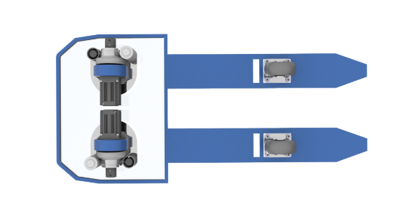
The unidirectional differential drive AGV chassis consists of two omnidirectional wheels, two steering wheels, and one drive unit. Its AGV trajectory simulation focuses on the arc segment of motion, neglecting geometric modeling during the angular transition stage. In warehouse automation and automotive manufacturing environments, this configuration is favored for its compact design and agile steering performance. With precise servo drive for AGV control, differential wheel speeds enable smooth path tracking and high-accuracy positioning—essential for path planning and motion prediction algorithms.
1.1 Unloaded AGV Arc Segment Simulation Steps
1.1.1 Reference Point Positioning
Place the AGV drive rotation center precisely on the predefined RF arc line. This serves as the reference origin of the simulation.
1.1.2 Steering Wheel Trajectory Circle Drawing
Using the drive rotation center as the circle’s origin and the distance to the steering wheel centers as the radius, draw the trajectory circle to represent motion.
1.1.3 Drive Alignment
-
Enter the “AL” command and select the drive mechanism as the target;
-
Define source and destination points sequentially while keeping the reference fixed;
-
Select a point at the lower end of the drive wheel centerline as the second source and any point on OA as the target;
-
Press the spacebar twice to complete the alignment, ensuring precise fit between drive axis and trajectory circle.

1.1.4 AGV Body Posture Calibration
-
Draw a tangent line from the arc center;
-
Execute the “AL” command and fix the AGV reference point;
-
Align the steering wheel center with the tangent point to finalize the calibration.

1.1.5 Danger Zone Definition
Using the circle’s center as the origin, draw inner and outer boundary circles. The annular area between them represents the AGV danger zone where obstacles are strictly prohibited.
1.2 Simulation Characteristics with Omniwheel Trailer
The omniwheel trailer moves in full posture synchronization with the AGV, following identical AGV trajectory simulation steps without additional parameter calibration. This synchronized motion greatly improves path consistency and system stability in confined spaces typical of warehouse automation.
2 AGV Trajectory Simulation with Non-Omniwheel Trailer
This configuration considers the coupled motion of the AGV and trailer, requiring additional calibration of trailer posture.
2.1 Core Simulation Steps
2.1.1 AGV Reference Posture
Perform AGV body posture calibration following the unloaded simulation method, ensuring the correct orientation alignment.
2.1.2 Trailer Coupling Calibration
Align the trailer coupling center precisely with the AGV’s tow bar center to maintain coaxial force transfer.
2.1.3 Trailer Steering Wheel Trajectory Circle
Using the reference center, draw a trajectory circle with the distance to the trailer steering wheel as the radius.
2.1.4 Trailer Posture Alignment
Draw a tangent line, execute the “AL” command, and align the trailer steering wheel center with the tangent point to complete calibration.

2.1.5 Boundary and Safety Zone
Draw the maximum boundary line covering both AGV and trailer outlines; the enclosed area defines the danger zone where no obstruction is allowed.
3 Bidirectional Differential Drive AGV Trajectory Simulation
The bidirectional differential AGV chassis adopts four omnidirectional wheels and two drive units, supporting bidirectional movement. Simulation must synchronize both front and rear drive mechanisms.
3.1 Unloaded AGV Simulation Steps
3.1.1 Front Drive Positioning
Place the front drive rotation center on the arc line as the reference base.
3.1.2 Rear Drive Calibration
Using the front drive center as origin and the distance between drive centers as radius, draw a circle intersecting the arc. Execute “AL” and align the rear drive center to the intersection.
3.1.3 Safety Zone Definition
Draw the overall AGV motion boundary to separate safe and restricted regions.
3.2 Loaded Simulation Features
This AGV type supports only omniwheel trailers; both postures remain synchronized, following the unloaded AGV simulation sequence.
4 Bidirectional Steering Wheel AGV Trajectory Simulation
This AGV uses four omnidirectional wheels and two steering modules. Magnetic navigation sensors are mounted on the body, differing fundamentally from differential drive systems.
4.1 Unloaded AGV Simulation Steps
4.1.1 Front Sensor Positioning
Place the front magnetic navigation sensor at the arc line as the calibration reference.
4.1.2 Rear Sensor Calibration
Using the front sensor as center, draw a circle with the distance between sensors as radius, intersecting the arc line. Execute “AL” to align the rear sensor center with the intersection point.

4.2 Simulation Of The Trajectory Of A Material Cart With Omnidirectional Wheels
The material cart's running posture is completely synchronized with the AGV. The simulation steps are consistent with those of an empty AGV, requiring no additional parameter adjustments.
Share:
Servo Motors and Drive Systems for AGVs: Selection Formulas, Key Technologies & Industrial Applications
Servo Motor Selection Guide: Achieving Precise and Efficient Control